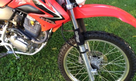
“This is a necessary evil. If you plan to switch to any type of led turn signals to your Honda CRF230L, you will need to switch out the turn signal flasher relay so your turn signals actually work”
Tools Needed:

- 5mm Wrench
- 6mm Allen Wrench
- Small Flat Head Screwdriver
Additional Supplies:
Instructions:
Intro:
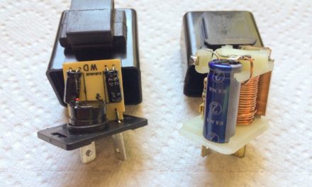
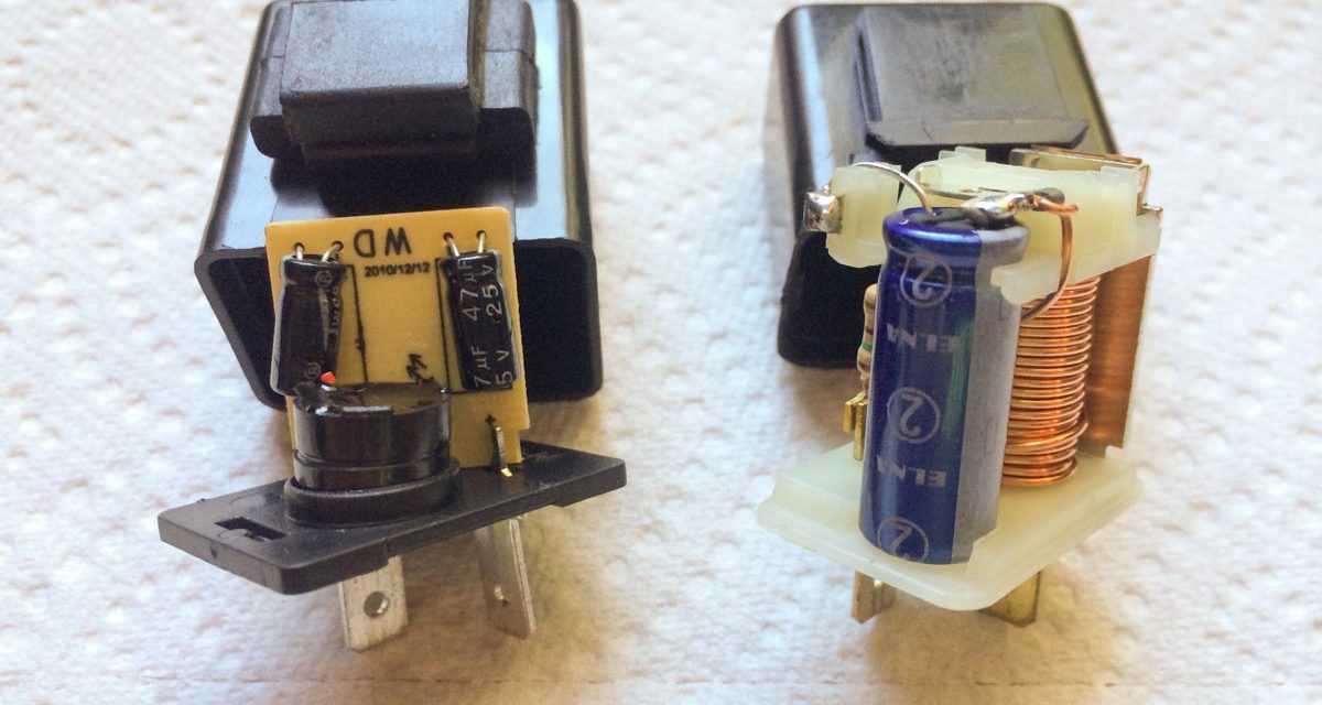
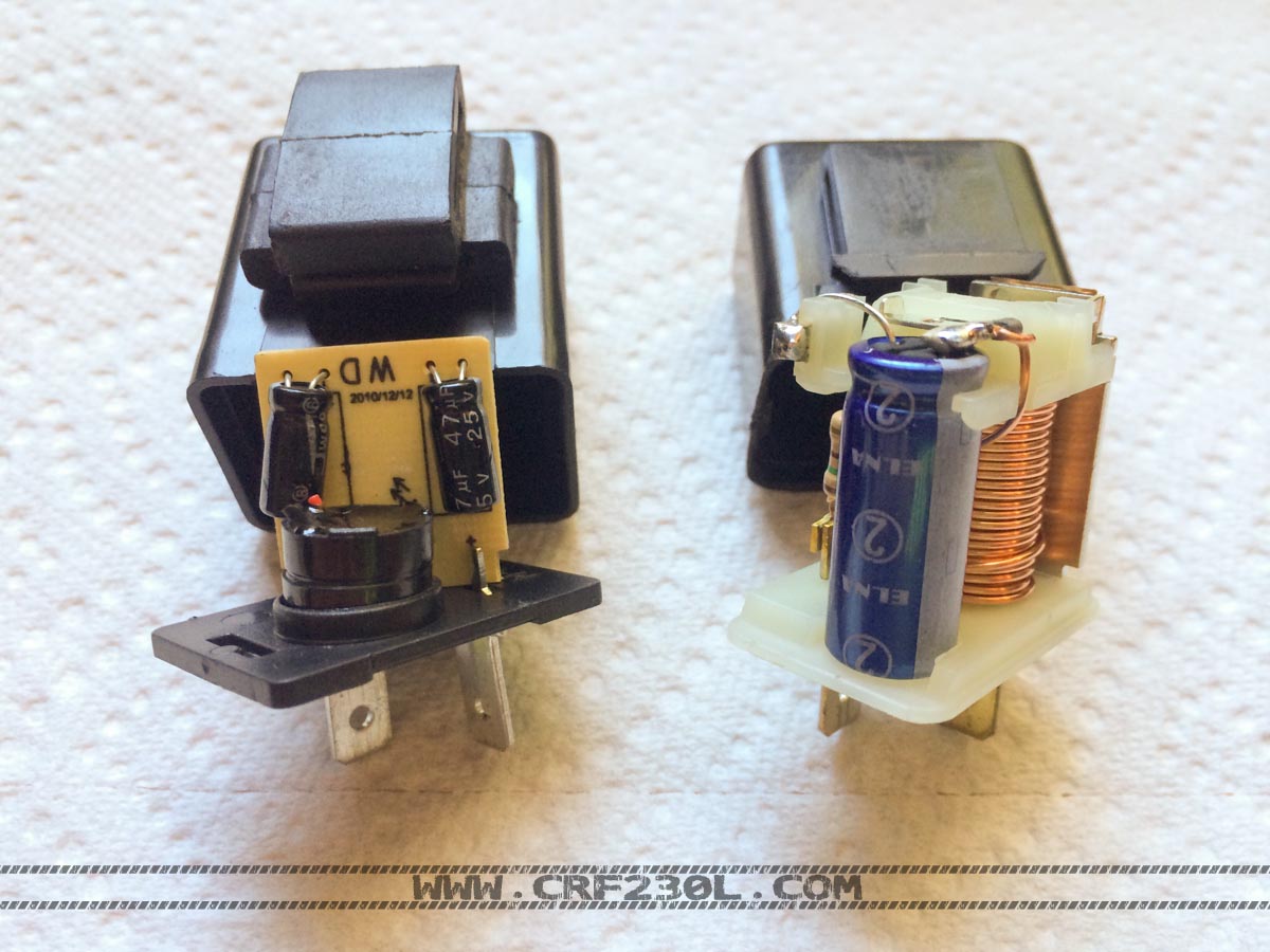
In the picture to the left you can see the aftermarket electronic relay on the left and the oem thermal relay on the right. This change will allow for the use of LEDs in the turn signal system. The LEDs do not draw enough current to trip the thermal style relay, meaning your turn signal may light up but not flash. This lets you know that you need to switch to the electronic style relay.
Step 1:
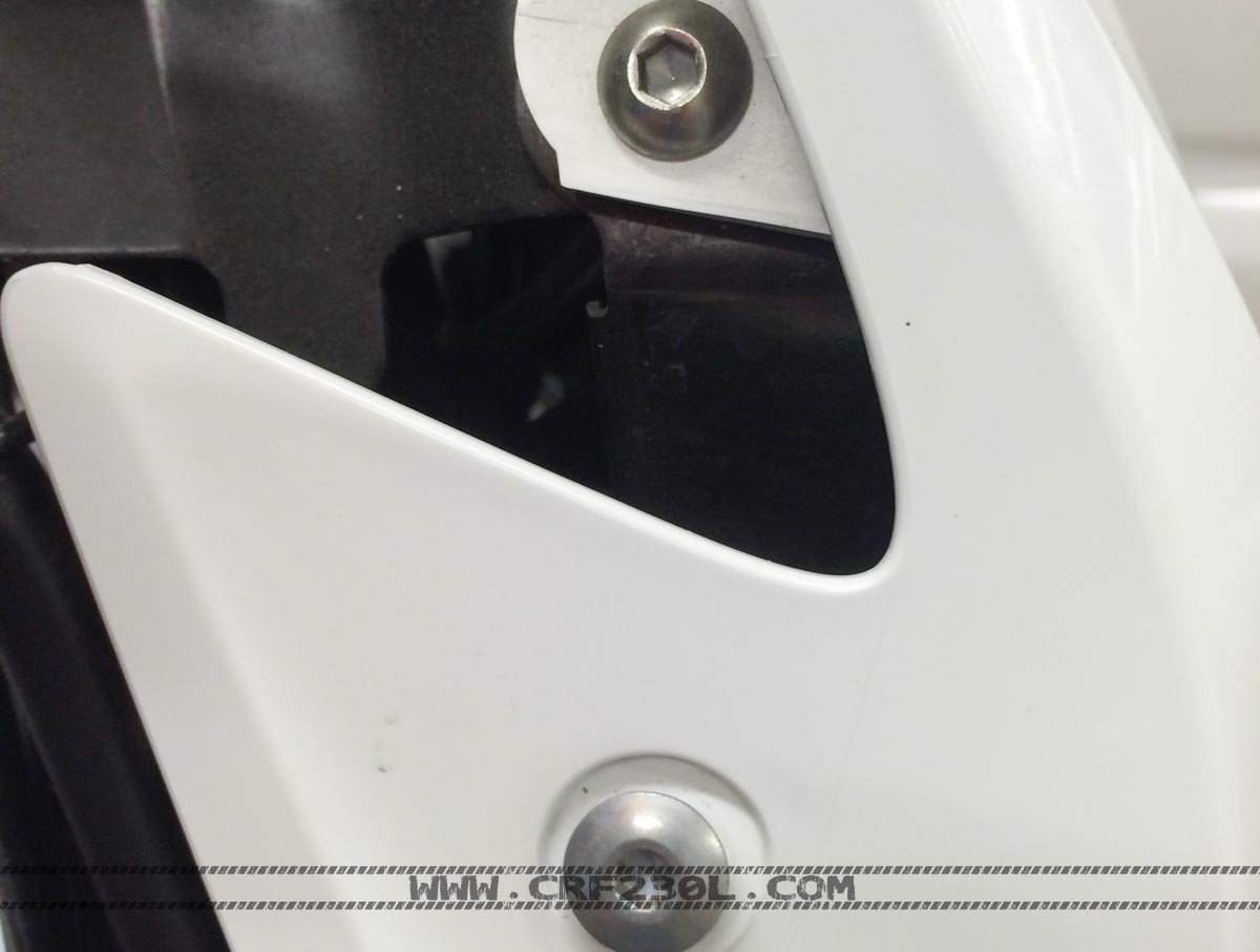
Start off by partially removing the headlight fairing. You will need to remove the two cap screws on each side using a 5mm and 6mm allen wrench respectively. At this point you can move it out of the way, you do not need to disconnect the headlight. Update: You can try to wrestle the relay off the mount without removing the headlight fairing if you want with a small flat head screwdriver from the backside of the triple clamp.
Step 2:
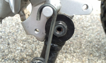
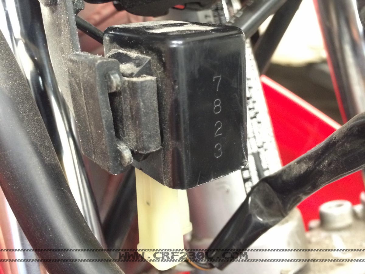
Remove the turn signal relay off the mounting tab. A small flat head screw driver can help the rubber mount over the tabs on the end of the mounting bracket on the bike. Unplug the wiring harness from the relay. Again, a small flat head screwdriver can help to remove the connector.
Step 3:
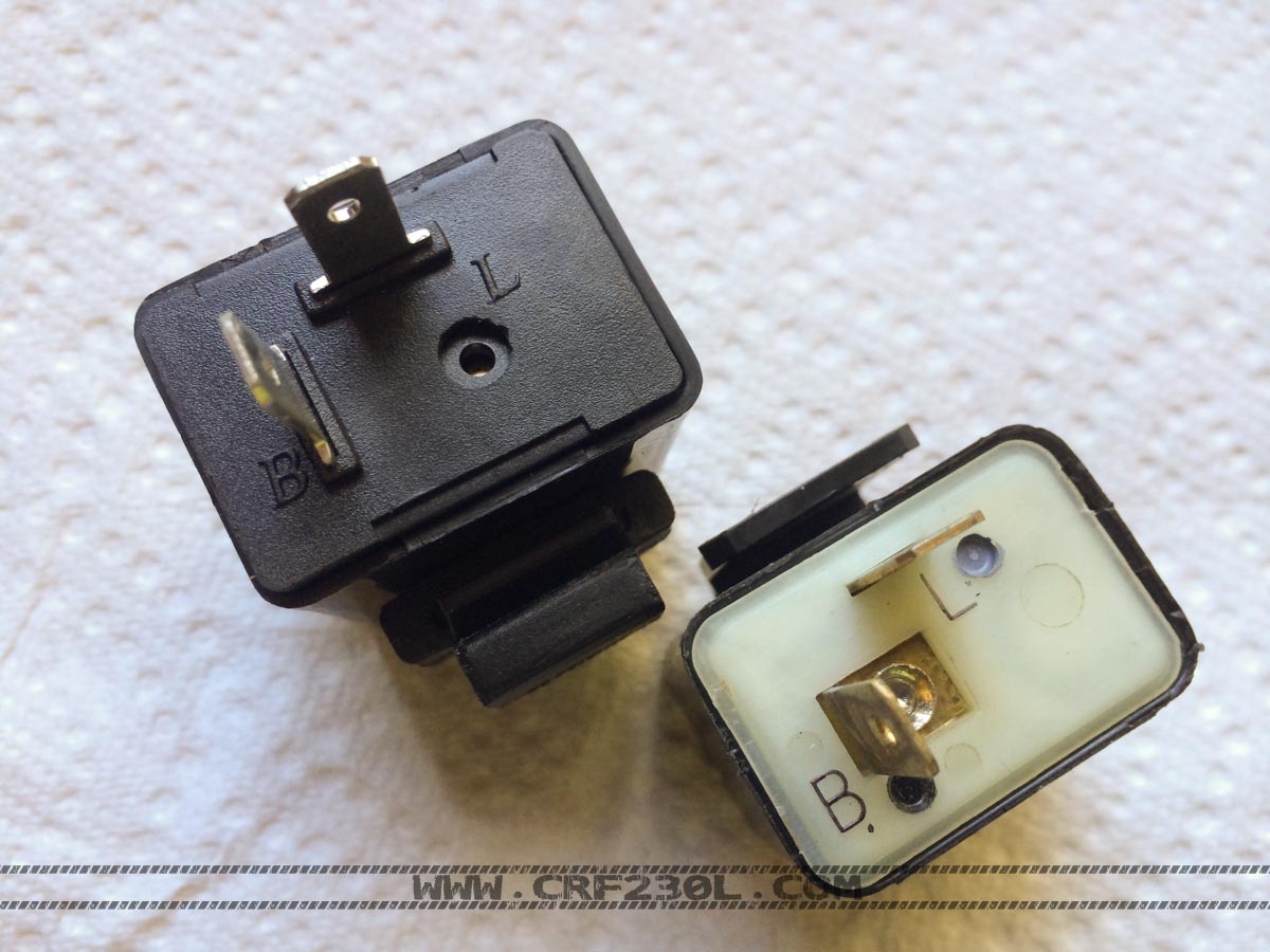
Take the rubber mount off the new relay and discard it. You will then take the rubber mount off the oem relay and move it to the aftermarket relay. This will allow you to mount the relay in the same orientation. You can see the new electronic flasher relay in the top left and the oem relay bottom right of the picture below. You can also use the adjustable rate relays that are now available. See above.
Step 3 (ALT):
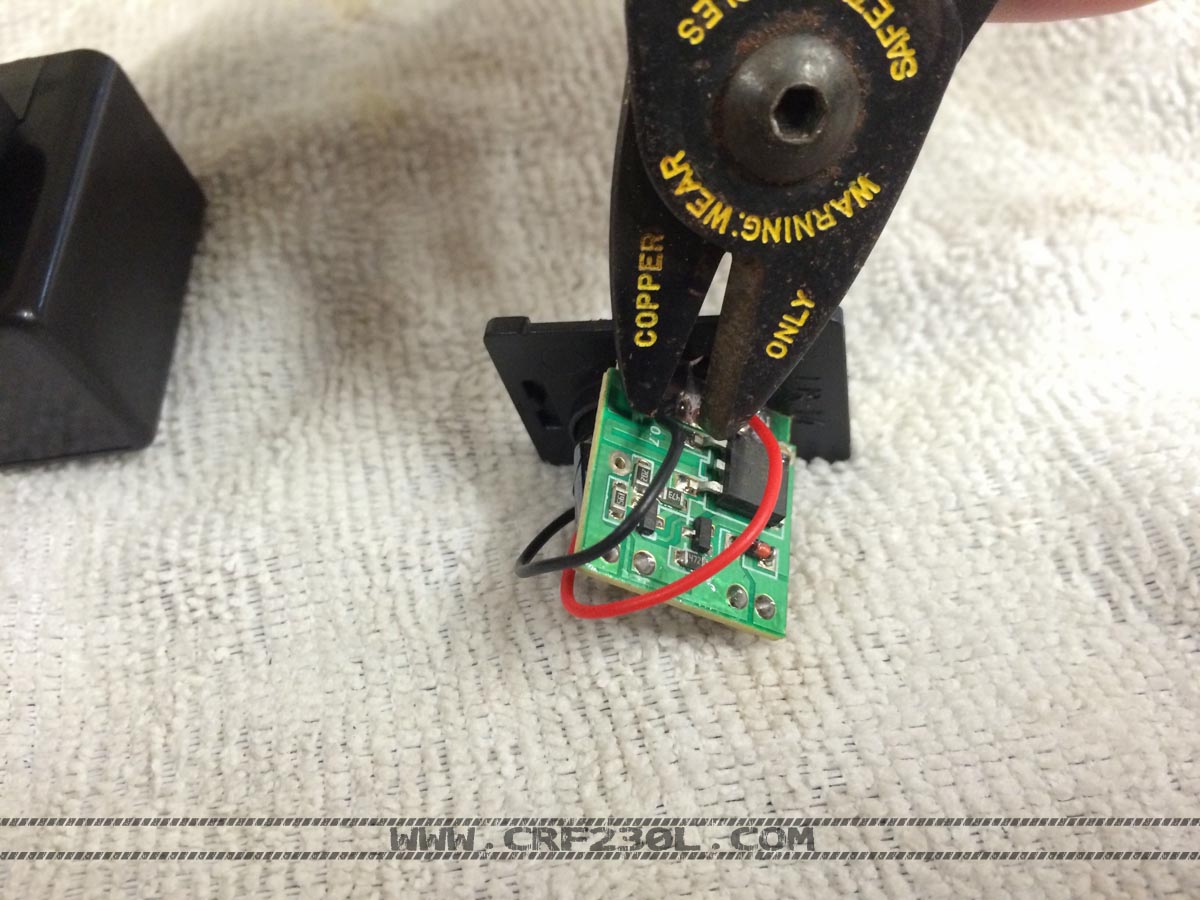
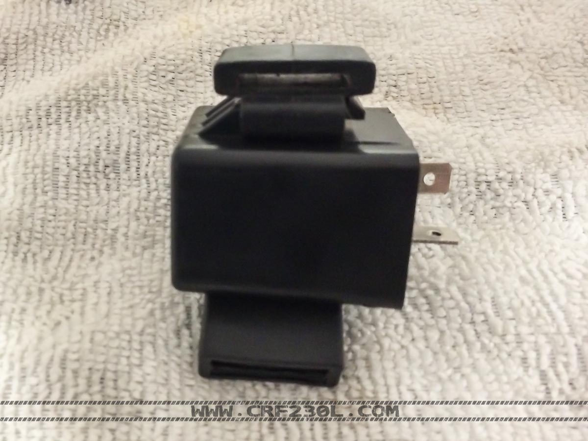
There are two types of relays available with two pins that look identical except a small hole in the base of one. This is for a buzzer that sounds when the flasher is engaged. This was shipped inadvertently and was modified to remove the buzzer. Pry open the relay case with a small flat head screwdriver. Once open snip both ends of the wires that loop over to the small circle buzzer mounted above the hole. This will only leave what is attached to the small circuit board and the two pins that your wires connect to.
Step 4:
Mount the relay back on the bike and plug the connector back in. It is on the opposing side but will function correctly, it will only plug-in in one direction. You will also notice in the picture above that the labeled terminals (L and B) are in the same orientation even though they mount in the plastic housing on opposite sides, You will want to check this on your relay in the event it is slightly different. If so, remove the terminals from the connector on the bike and swap them if needed. In this case no change was needed, just plug the harness back in. Re-attach the headlight fairing and admire your handiwork.

